
In the HVAC and refrigeration industry, whether you’re designing commercial cooling systems, specifying equipment for industrial facilities, or maintaining existing installations across the GCC region, a solid understanding of refrigeration fundamentals is essential. A refrigeration process diagram serves as the blueprint for how cooling systems function, mapping the continuous cycle that maintains precise temperature control in everything from large-scale air conditioning units to specialized cold storage facilities.
What Is a Refrigeration Process Diagram?
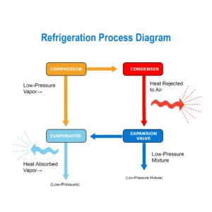
A refrigeration process diagram represents a closed-loop system where thermal energy is transferred from one location to another. It serves as a visual means to explain how the refrigerant circulates in the system, constantly changing its pressure and phase states in order to achieve positive cooling.
The basic principle is the same: refrigeration doesn’t create cold, it removes heat. The diagram maps how refrigerant acts as a heat transport medium, absorbing thermal energy from the conditioned space and rejecting it to the external environment. This applies uniformly to air conditioning systems, chillers, and refrigeration equipment.
The Four Essential Stages of Refrigeration
Compression: Building Pressure and Temperature
The refrigeration cycle begins at the compressor, the mechanical heart of the system. Low-pressure refrigerant vapour enters the compressor and is compressed into high-pressure, high-temperature gas. This compression greatly increases the energy level and temperature of the refrigerant while reducing its volume.
Various compressor technologies are in use in modern HVAC: reciprocating, scroll, or screw compressors, each of which brings advantages in terms of applications and capacity ranges. Compressor efficiency impacts the costs of operation and system reliability for commercial chillers and large air conditioning applications typical throughout the Middle East.
Condensation: Heat Rejection
Critical heat rejection occurs in the condenser coil after compression of the superheated refrigerant vapor. The refrigerant in this state releases its accumulated thermal energy to the surrounding environment through air-cooled or water-cooled heat exchange methods.
During condensation, with the loss of heat the refrigerant undergoes its phase change from hot gas to high-pressure liquid. This process occurs at constant temperature and pressure; thus, the condenser assumes great relevance to the efficiency of the system in general. This, coupled with the peculiarly harsh climatic conditions of the GCC region, requires that extra care be taken in the design of condensers and their maintenance, such as washing the coils regularly, to assure efficient heat transfer and prevent system overload.
Dilation: Pressure Reduction
As the high-pressure liquid refrigerant passes through the expansion device, it will create a designed pressure drop. The component-this could be either the thermostatic expansion valve (TXV), electronic expansion valve (EEV), or fixed orifice-serves to rapidly drop the pressure and initiate partial refrigerant evaporation.
This “flashing” effect creates a cold, low-pressure liquid-vapor mixture that is in an ideal state for effectively absorbing the heat in the next stage. Advanced expansion valves further regulate the flow of refrigerant dynamically, matching system capacity to cooling demand while protecting the compressor against liquid refrigerant return, which could cause mechanical damage.
Evaporation: Heat Absorption
Actual cooling takes place at the evaporator. The cold refrigerant mixture passes through the evaporator coil, which absorbs heat from either surrounding air or process fluids. While absorbing thermal energy, the remainder of the liquid refrigerant evaporates into low-pressure vapor.
The fans, in the case of air conditioning, circulate air over the evaporator coils to transfer heat from the space being conditioned into the refrigerant. Chillers cool water or glycol solutions for use in process cooling or space conditioning. This continuous absorption of heat maintains desired temperatures throughout commercial buildings, industrial facilities, or specialized applications.
The now-warmed refrigerant vapor returns to the compressor and completes the cycle and the process begins again.
Reading a Refrigeration Process Diagram
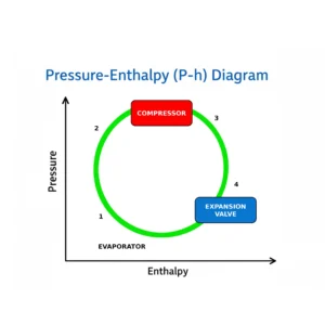
Most professional refrigeration diagrams include P-h charts, which plot thermodynamic properties at each stage in the cycle. Such technical diagrams help HVAC engineers and technicians to work out system performance, capacity requirements, and operational diagnosis.
Key components of a complete refrigeration process diagram include:
- Refrigerant flow direction indicating the continuous circuit path
- Component identification marking compressor, condenser, expansion device, and evaporator locations
- Pressure zones distinguishing high-pressure and low-pressure sides of the system
- Temperature indicators showing thermal conditions throughout the cycle
- Phase-change markers showing transitions between liquid, two-phase mixture and vapor states
- State points numbered for reference in thermodynamic calculations.
Practical Applications Across HVAC Systems
Understanding the refrigeration process diagram enables better specification and maintenance of HVAC equipment. Whether you are dealing with rooftop packaged units, split systems, chillers, or specialized cooling equipment, basically the same fundamental cycle applies-only variations in scale, refrigerant type, and component design.
This knowledge will be of even greater value to HVAC professionals operating in the GCC region when:
- Equipment selection for particular climate conditions and application needs
- Troubleshoot performance issues by identifying which stage of the cycle has problems.
- Effective system design and selecting appropriate components can optimize energy efficiency.
- Ensuring reliable operation at high ambient temperatures
- Defining maintenance needs to ensure long-term system performance.
Unusual frost patterns, inconsistent temperatures, or high energy consumption generally are caused by some malfunction in one of these four basic processes. In addition, dirty condenser coils limit heat rejection capacity, resulting in increased compressor workload. Refrigerant charge problems upset the whole cycle, compromising cooling capacity and perhaps damaging equipment.
The Value of Technical Understanding
Understanding the refrigeration process diagram allows HVAC distributors, contractors, and facility managers to make informed decisions about system selection, installation, and maintenance. This knowledge allows proper equipment specification for difficult applications and effective communication with engineers, technicians, and end users.
With the advancement of modern HVAC technology, systems continue to boast increased efficiency ratings, environmentally friendly refrigerants such as R410A, R32, and R134A, and advanced controls that also include inverter-driven compressors. The basic four-stage refrigeration cycle, however, has remained unchanged-a time-tested process that reliably delivers the precise temperature control so important in commercial, industrial, and institutional applications for a wide range of industries in various regions.
Conclusion
Whether you’re an HVAC professional, facility manager, or contractor working in the GCC region, mastering the refrigeration process diagram is fundamental to delivering reliable, efficient cooling solutions. At Foster International, we understand the critical importance of quality HVAC equipment and technical expertise in meeting the demanding climate conditions of the Middle East.
Ready to optimize your HVAC systems? Contact our team today to discuss your specific cooling requirements and discover how our comprehensive range of air conditioning and refrigeration solutions can help you achieve superior performance and energy efficiency.

